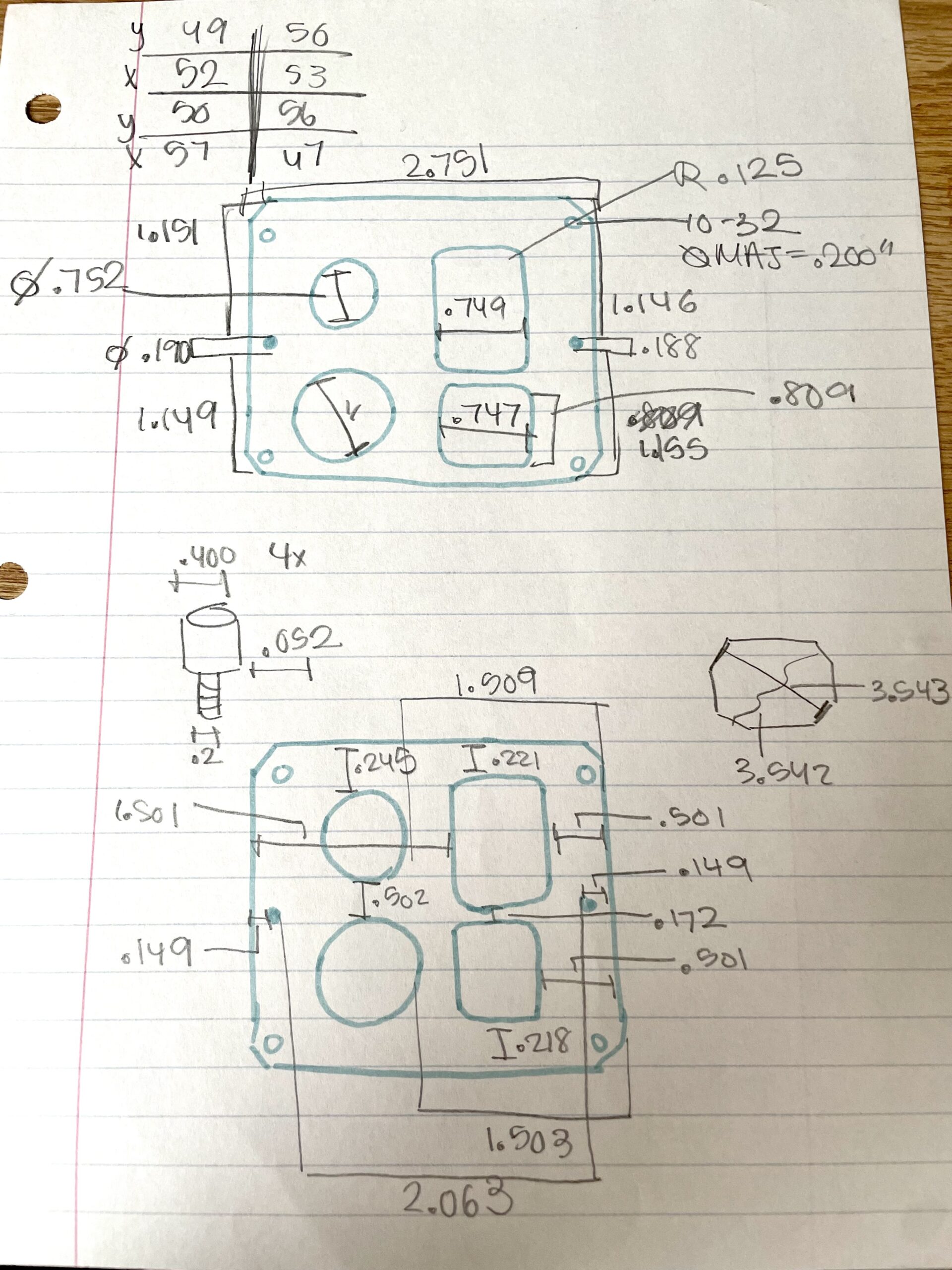
SKETCH:
This is a sketch of what was completed in class. Note that there are conflicting and overdimensioned parts (particularly tin regards to the small holes on the side of the gasket). This ultimatly was the cause of the gasket not fitting correctly which will be discussed further at the end of this page.
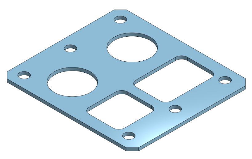
CAD:
Here is an screenshoot of the CAD Model sketch from Onshape used to machine the gasket. Note that despite conflicting dimensions, the holes were placed at 0.148 in away from the edge of the gasket. One of the possibility for error was that these wholes were mirrored over the center line instead of being dimensioned twice, which is not a reliable way to sktch dimensions jsut in case the part is not perfectly centered across the axis.
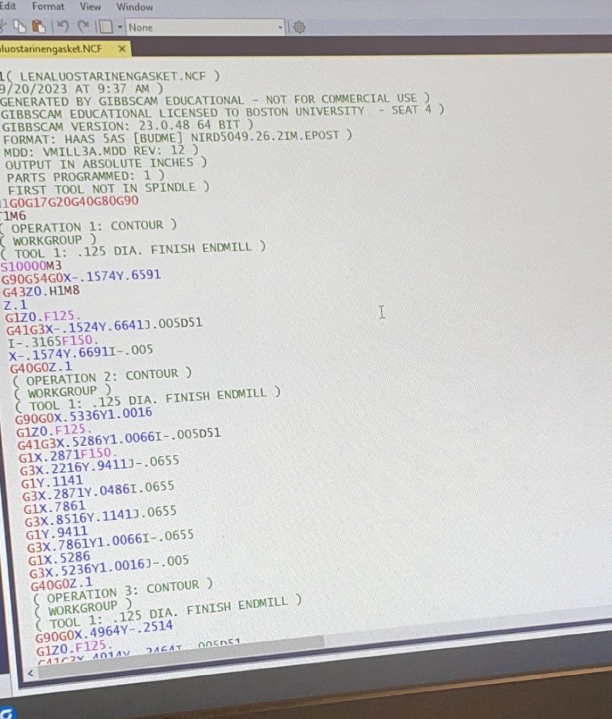
GIBBSCAM:
This is an image taken in EPIC of the code generated from GibbsCAM. GibbsCAM was used to create the machining paths and directions for the CNC Machine to follow based on the Onshape Model above.
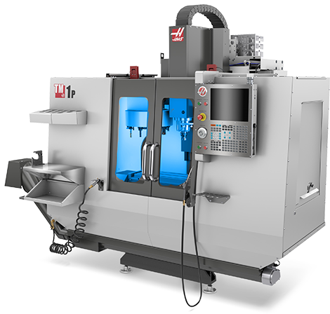
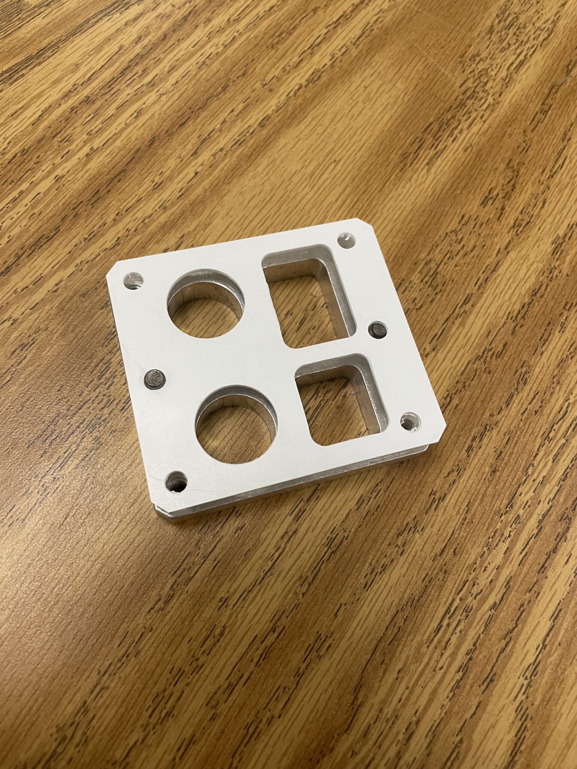
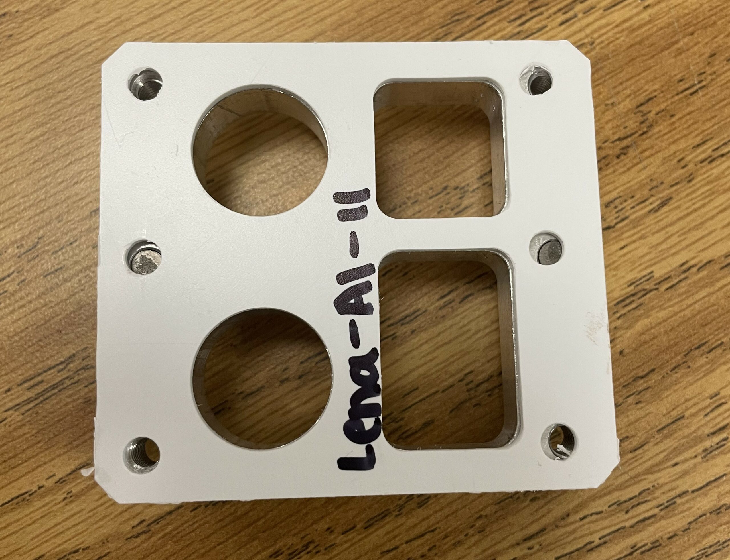
Above is an image of the CNC Mill used to machine the gasket. To the right is an image of the final product on of the part (#11). All of the holes and sides line up except for the one row of holes which are placed too far left for the gasket to fit onto the block. As discussed in earlier paragraphs on this webpage, this error could be due to the over-dimensioned sketch of the block that was produced when initially measuring the part, or it could be due to a CAD error when mirroring these holes across the Y-axis.
